Working with the Data Flow Diagram model
The Data Flow Diagram model is a model that can be used to model a software system in an easy-to-learn and lightweight fashion.
The Data Flow Diagram model consists of two different metamodels: The Data Flow Diagram describing the nodes, flows and behavior of nodes of the software system. The Data Dictionary describes the attributes of nodes and flows.
Data Flow Diagram
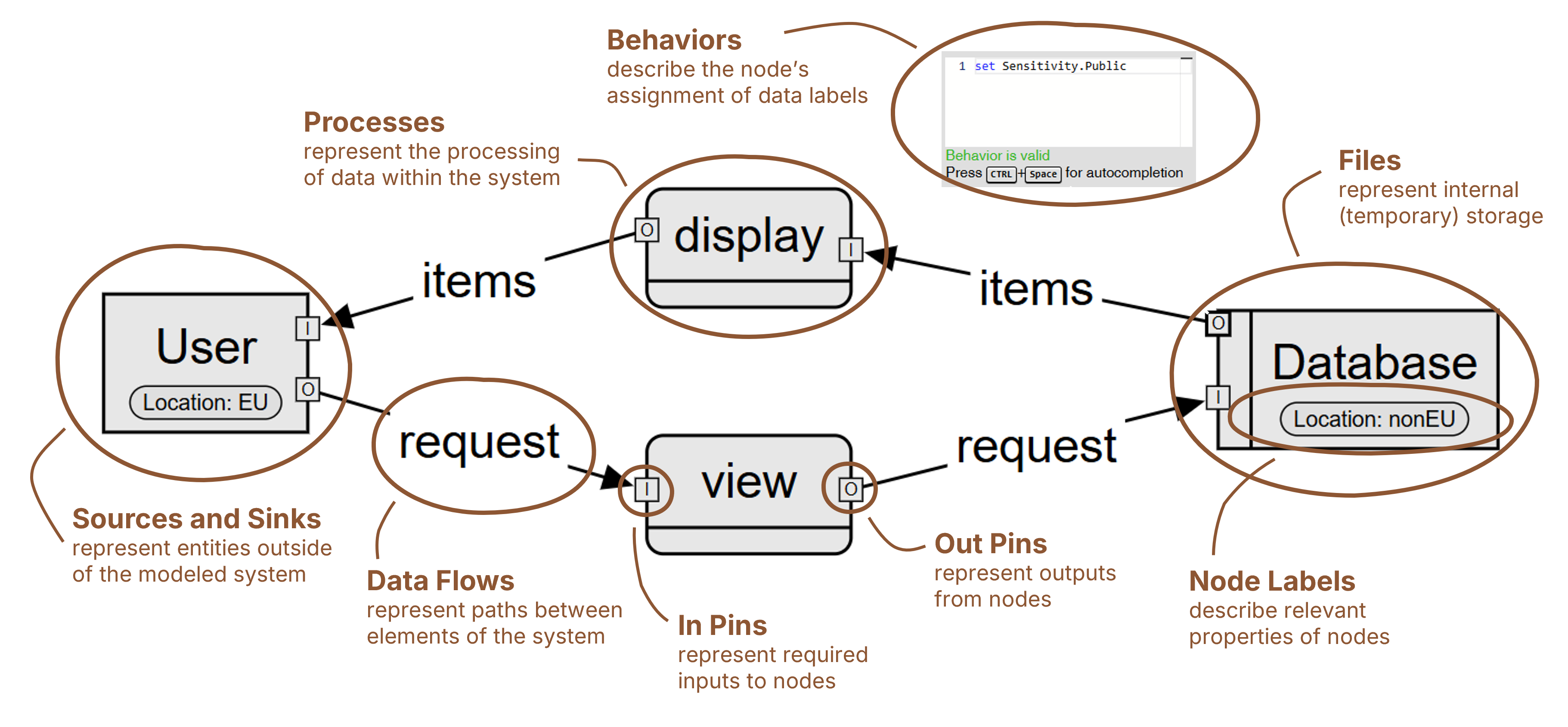
The Data Flow Diagram contains Nodes that describe a step in the processing of data though the modelled software system. The model distinguishes from the following three types of nodes:
| Node Element | Semantic Usage |
|---|---|
| Storage Node | Data is stored/retrieved at this node |
| Input/Output Node | Data enters/exits a system at this node |
| Function Node | Data is processed at this node |
In Addition a Node can have Ports that denote that data flows to or from a node. A Input Pin denotes that data (typically one) enters the node. An Output Pin denotes that data exits the node.
The Ports of Nodes can be connected using Flows that denote that the data from an Output Pin of one node flows into the Input Pin of another.
Each Output Pin of a Node can have an Behavior that describes properties of the data flowing out of this node. This Behavior may depend on the data flowing into the nodes though it's Input Pins.
Next, a Node can also have Node Labels that describe properties of a Node .
Data Dictionary
The Data Dictionary contains a set of Label Types and corresponding Label Values that describe the properties of nodes and data in the Data Flow Diagram. Additionally, it stores the Behaviors outlined in the previous section, allowing for reuse.
Example of an Label Type and Label Values
For example for modeling a location of a system, one might model the following: A Label Type Location with Label Values EU, NA, Asia